Multi-Camera Vision (ULTRA R5000 and R9000)
Multi-Camera Vision is a patent-pending available feature that provides a view of a digital design file overlaid or superimposed onto material placed into the processing envelope of the laser system. Strategically placed cameras capture the entire processing area and a close-up of material placed into the laser system. Through the Laser System Manager (LSM) the user controls camera views along with movement, rotation, and scaling of the design file view.
Full Area View
A camera is located on the inside of the top door and points directly down to the processing area when open.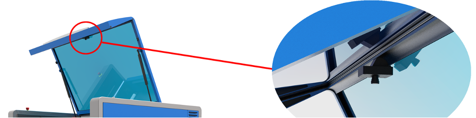
Illustration of Top Door Camera
This door camera provides a distortion corrected image of the entire processing area and the material(s) placed on the Multifunction Material Support Structure.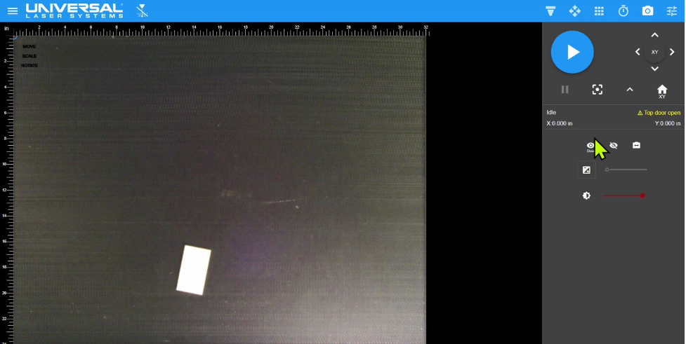
Screen shot of entire material processing area as viewed in the Laser System Manager (LSM) captured by the top door camera. The entire 32 x 24 in. (831 x 610 mm) processing area of the ULTRA R5000 is visible along with an image of the 1.5 x 3 in. (38 x 76 mm) white plastic material placed on the Multifunction Material Support Structure.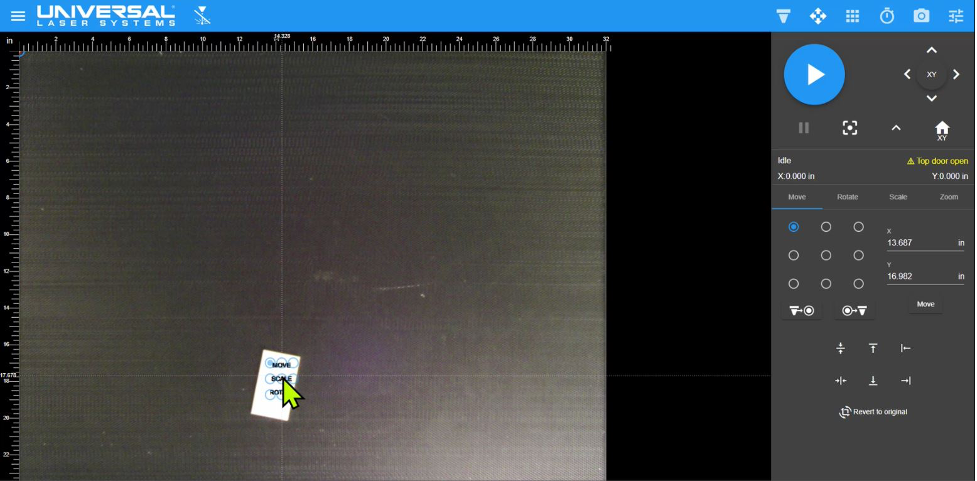
Initial drag-and-drop positioning of design file onto door camera image of material on the Multifunction Material Support StructureHigh Resolution Close Up View
A second camera is attached to the optics carriage assembly. This camera is positioned directly over the material being processed.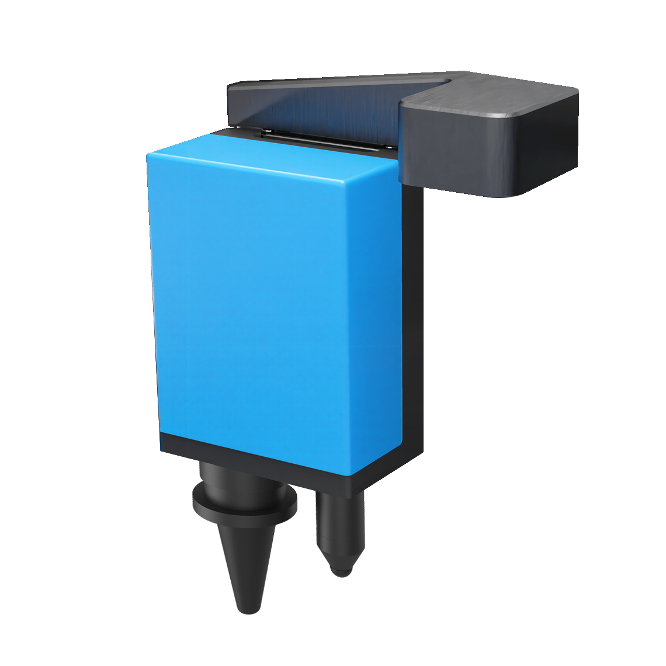
Illustration of camera attached to top of carriage
This carriage camera produces a high resolution close-up view of the material and is ideal for visually assisting precision placement of design files onto smaller parts. This camera is capable of capturing less than 15 square inches (9700 square millimeters) of area per photo or less than two percent of the total processing area. If the part is larger than the camera’s field of view, multiple close-up photos (tiles) are taken and instantly stitched together.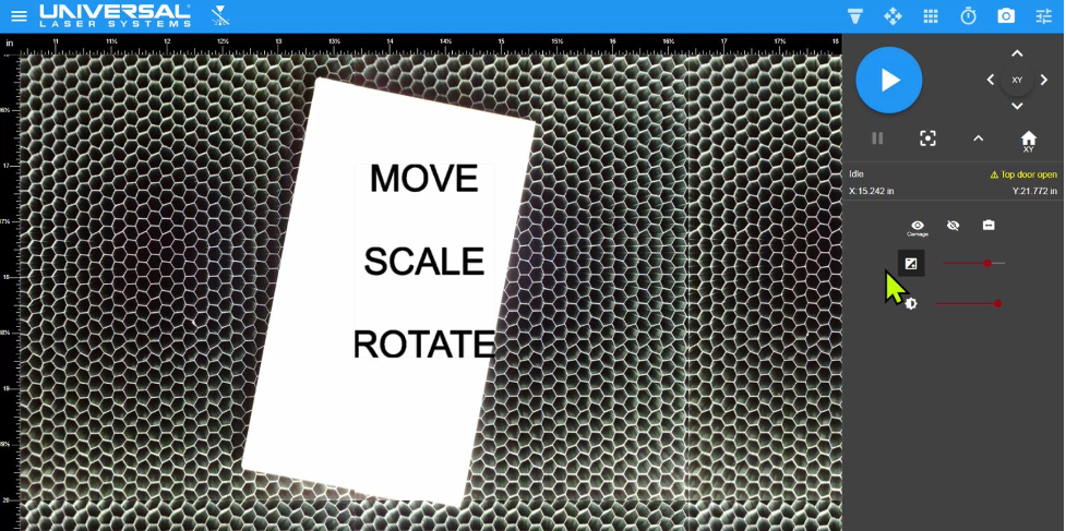
Close-up view in the Laser System Manager (LSM) of the material placed on the Multifunction Material Support Structure provided by the carriage camera. In this example the design file consisting of text (MOVE, SCALE, and ROTATE) is positioned over the material. The design file can be any laser compatible graphic.
Sizing and Final Positioning of Design Files
The Laser System Manager (LSM) facilitates precise positioning and sizing of design files using controls for Move, Rotate, and Scale with real time visual feedback made possible through advanced machine vision algorithms.
Using the Rotate controls, the design file was rotated. Any angle of rotation is possible.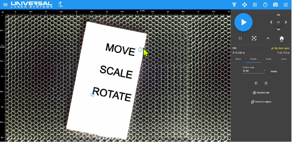
Design file rotated using controls in the LSM. In this example, the design file was rotated clockwise to match the rotation of the material.
Using the Scale control, the design file was resized.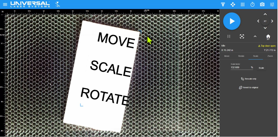
Design file Scaled using controls in the LSM. In this example, the design file was made larger or scaled up.
Using the Move control, the design file was placed in final position onto the material view.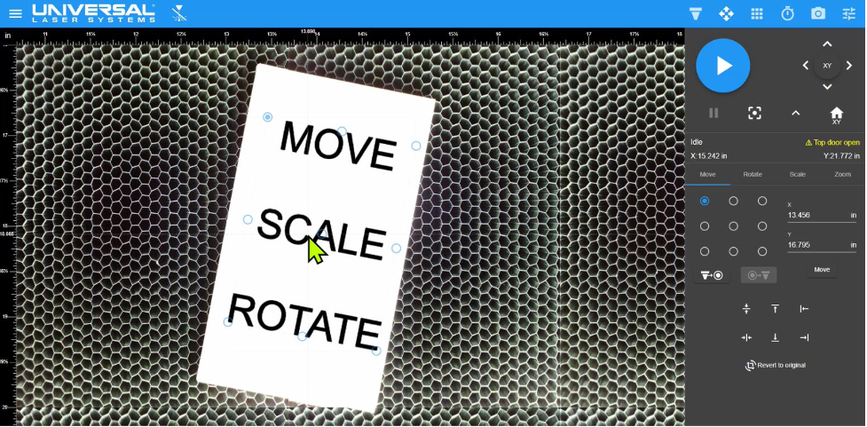
Design file moved using controls in the LSM. In this example, the design file was moved toward the center of the material.
Another use for camera technology is registration. With registration, a camera locates and determines the exact positions of registration marks on materials inside the laser system. Software adjusts the predefined cut-path to fit the material. To learn more about this feature, see Universal Camera Registration Innovation.
DISCOVER

